Home
Battlefield Hex 3D User Guide, v1.0, 4 Jan 2024
Contents
- Map Interface
- General Panel
- Basic Movement Panel
- Modal Actions Panel
- Immediate Actions Panel
- Line of Sight Modifiers Panel
- Coordinate Panel
- Dead Ground Panel
- How To…
- How to place the source marker
- How to place the target marker
- How to calculate Line of Sight
- How to calculate Dead Ground
- How to view the map from a specific hex
-
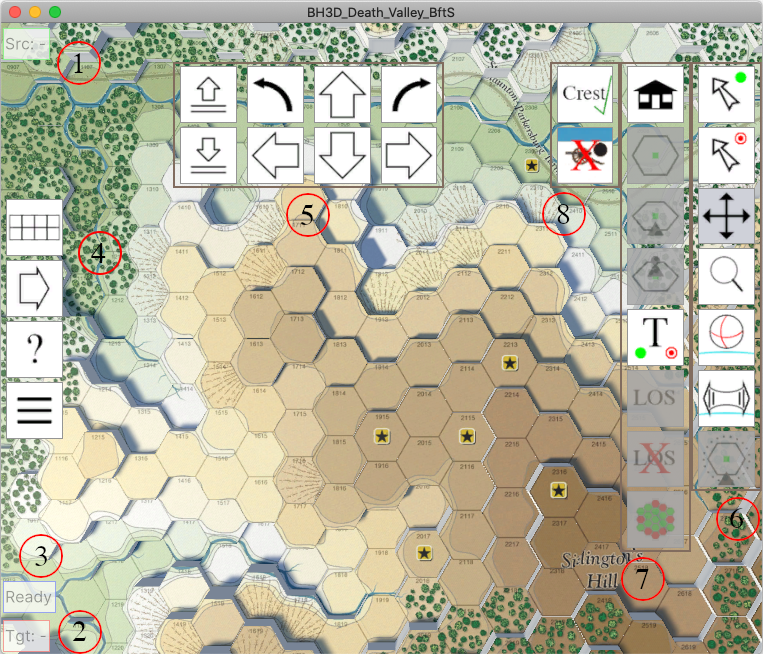
Source hex information: This is the information for the currently selected source hex, consisting of the terrain base
elevation level and a list of the various terrain types present (as given on the module’s Terrain Effects Chart). For
guidance on how to select the source hex, see ‘How to place the source marker’.
-
Target hex information: This is the information for the currently selected target hex, consisting of the terrain base
elevation level and a list of the various terrain types present (as given on the module’s Terrain Effects Chart). For
guidance on how to select the target hex, see ‘How to place the target marker’.
- Status: State messages, such as the reason for a blocked Line of Sight are shown here.
-
General panel: Controls to show/hide the Basic Movement Panel, show the current map’s terrain key, show the help page
and return to the title screen. See ‘General Panel’.
-
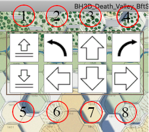
Basic movement panel: Controls for moving the viewer in simple ways, being move forward, move backwards, move left, move
right, move up, move down, turn left, turn right. The movement and turning increments are fixed amounts. See
‘Basic Movement Panel’.
-
Modal actions panel: Controls to set the current mouse mode and behaviour. These are place the source marker in a hex,
place the target marker in a hex, move forward/backwards/sideways in the current plane, zoom in/out, rotate the viewer
up/down/left/right, rotate the viewer left/right, orbit around the source marker hex. See ‘Modal Actions Panel’.
-
Immediate actions panel: Controls to perform immediate actions. These are go to the home viewing location, go to the
current source marker hex and look down onto it, point the viewer at the source marker hex, place the viewer at ground level
at the source marker hex, use text entry to place the source and target markers, calculate the Line of Sight between the
current source and target marker hexes and show the feedback on the map, remove the Line of Sight feedback from the map and
calculate Dead Ground from the current source marker hex. See ‘Immediate Actions Panel’.
-
Line of sight modifiers panel: Controls that affect Line of Sight calculation. These are: to include the Crests optional
rule and to perform the calculation as though an artillery unit is the source. The latter option is only available in the
Battles for the Shenandoah expansion module. See ‘Line of Sight Modifiers Panel’.
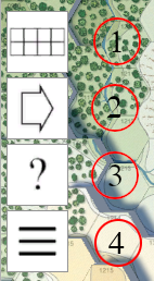
- Toggle Basic Movement Panel on/off.
- Show the map terrain key. Left-click on the map terrain key panel to hide it again.
- Show the help page.
- Return to the title screen.
-
Move up: moves the viewer vertically upwards a preset distance increment above the map and automatically angles the
viewer to provide a view of the hexes around the hex that is below the viewer.
- Turn left: turns the viewer a preset angle to the left.
-
Move forwards: moves the viewer a preset distance forwards. Automatically adjusts the viewer’s vertical position to be
above the map terrain level.
- Turn right: turns the viewer a preset angle to the right.
-
Move down: moves the viewer vertically downwards a preset distance increment above the map and automatically angles the
viewer to provide a view of the hexes around the hex that is below the viewer.
-
Move left: moves the viewer a preset distance to the left. Automatically adjusts the viewer’s vertical position to be
above the map terrain level.
-
Move backwards: moves the viewer a preset distance backwards. Automatically adjusts the viewer’s vertical position to be
above the map terrain level.
-
Move right: moves the viewer a preset distance to the right. Automatically adjusts the viewer’s vertical position to be
above the map terrain level.
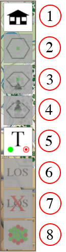
Click on a button to set the current mouse mode. A white background button (e.g. button 1 in the diagram) is an available
mode. A pale grey background button (e.g. button 3 in the diagram) is the currently selected mode. A dark grey translucent
button (e.g. button 7 in the diagram) is not available until a prerequisite has been met, e.g. the Orbit Source mode is not
available until a source marker has been placed on the map.
-
Place source mode: (Left-) Click on a map hex to place a green source marker. The hex information for the chosen hex
is displayed in the top left corner of the screen. Placing a source marker makes a number of other modes and actions
available on the panels. There can be a maximum of one source marker on the map. The source marker cannot be placed in the
same hex as the target marker. Clicking in the area around the map that is not a user interface control removes the
currently-placed source marker.
-
Place target mode: (Left-) Click on a map hex to place a red target marker. The hex information for the chosen hex is
displayed in the bottom left corner of the screen. Placing a target marker makes a number of other modes and actions
available on the panels. There can be a maximum of one target marker on the map. The target marker cannot be placed in the
same hex as the source marker. Clicking in the area around the map that is not a user interface control removes the
currently-placed target marker.
-
Move view mode: (Left-) Click-drag up/down/left/right to move the view of the map vertically and horizontally. The
viewer’s height above the map will adjust automatically to ‘walk up’ the terrain as necessary.
- Zoom view mode: (Left-) Click-drag up/down to move the map view in/out.
- Rotate view mode: (Left-) Click-drag up/down/left/right to rotate the map view vertically and horizontally.
- Turn view mode: (Left-) Click-drag left/right to rotate the view horizontally.
-
Orbit source mode: (Left-) Click-drag left/right to rotate the map view around the current source hex. A source marker
must be on the map for this mode to be available.
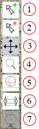
The buttons on this panel are not modal. Clicking a button performs an immediate action and does not affect the current mode
set on the Modal Actions Panel. A white background button (e.g. button 1 in the diagram) is an available mode.A dark grey
translucent button (e.g. button 2 in the diagram) is not available until a prerequisite has been met, e.g. the Look At action
is not available until a source marker has been placed on the map.
-
Home view: places the viewer above the centre of a preset map sheet, looking directly down. Use this action to reset
the viewer to a known state if manually moving the viewer has caused it to become disorientated.
- Look down: places the viewer directly above the current source hex, looking directly down at it.
-
Look at: rotates the viewer at its current map position, in order to place the current source hex in the centre of the
window. A source marker must be on the map for this action to be available.
-
Stand on: places the viewer slightly above the current source hex, looking levelly across the map. Clicking Stand On
again returns the viewer to the position before Stand On was first pressed. In effect, the viewer’s position before using
Stand On is remembered and returned to afterwards. A source marker must be on the map for this action to be available.
-
Text coordinates: opens a sub-panel which allows source and target hexes to be chosen by their textual map sheet hex
coordinates. See ‘Coordinate Panel’.
-
Line of Sight: calculates the LOS from the current source hex to the current target hex. Green-highlighted hexes are
clear LOS, while red-highlighted hexes are blocked LOS. The changeover from clear to blocked indicates the position and
terrain feature that caused the block. Status text in the bottom-left of the window provides additional information, such
as the relevant rule book clause. The LOS green/red feedback remains on the map until manually cleared using ‘Clear Line of
Sight’ or a new LOS or Dead Ground is calculated. A source marker and a target marker must be on the map for this action to
be available.
-
Clear Line of Sight: Removes any current LOS or Dead Ground green/red feedback from the map. LOS/Dead Ground feedback
must be on the map for this action to be available.
-
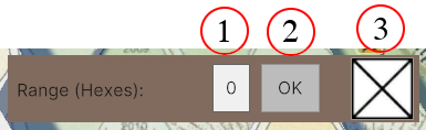
Dead Ground: clicking this button opens a Dead Ground dialog. Set the hex range from the current source hex for the
dead ground analysis (0 indicates no limit) and press OK to perform the analysis. Hexes visible from the source hex are
highlighted in green, while those that are not visible from the source hex are highlighted in red. The Dead Ground green/red
feedback remains on the map until manually cleared or a new LOS or Dead Ground is calculated. A source marker must be on
the map for this action to be available. WARNING: This calculation process runs to completion and cannot be interrupted
once started, so try increasing ranges in the dialog to determine the timeliness of your specific computer hardware before
trying range 0 (unlimited range).
This panel contains options to modify Line of Sight and Dead Ground calculation. If changed, they only affect subsequent
calculations and not any current calculation feedback that may be on the map. A ‘tick’ indicates that the option is active,
while a ‘X’ indicates that it is not active.
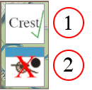
-
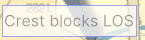
Crest optional rule: click to toggle the state between active (‘ticked’) and inactive (‘X’). Applies the Crest rules
to LOS and Dead Ground calculations.
-
Artillery and Cornfields: click to toggle the state between active (‘ticked’) and inactive (‘X’). Applies the rule
that firing artillery (‘ticked’) is affected differently to non-artillery (‘X’) by the presence of cornfields for LOS and
Dead Ground calculations. See BB 2W9.48. This option only applies to the Battles for the Shenandoah expansion.
This modal panel enables the setting of the source and/or target hexes by using their text coordinates. No other controls
are available while the panel is open. Close the panel in order to return to the normal map interface.
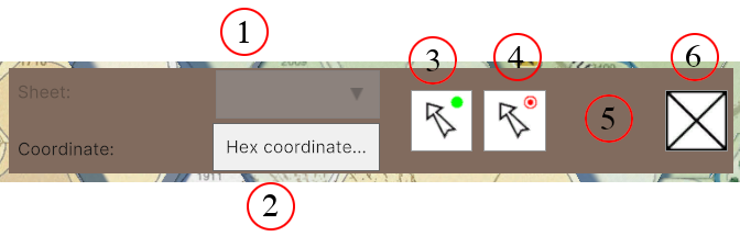
-
Sheet identifier: a drop-down list of the sheet identifiers for the map set of the displayed mapping. If greyed out,
then there is only one map sheet, so the identifier is unnecessary. Click on the drop-down to open it and click on the
required map sheet entry to select it.
-
Coordinate: enter the required hex coordinate in this text entry box. A leading zero, e.g. 0114, is not required, but
can be entered.
- Place source marker: click to place the source marker at the identified hex.
- Place target marker: click to place the target marker ay the identified hex.
-
Action success/fail feedback area: if the place source/target action is successful, a green tick is shown in this area,
otherwise a red ‘!’ is shown here.
- Close panel: closes the panel.
To use, select the required map sheet (if available), then enter the required hex coordinate for the map sheet, then click
on ‘Place source marker’ or ‘Place target marker’. If the identified hex is found on the selected map sheet and no marker is
already present at that hex, then the marker is placed on the map and the view is centred above that hex and a green tick is
shown on the panel. If the action fails, then no marker is placed and the existing markers remain where they are and a red ‘!’
is shown on the panel. When finished, click ‘Close panel’ to return to the mapping interface.
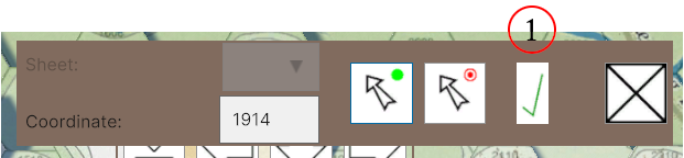
- Success: a tick is shown as a marker was successfully placed at hex 1914.
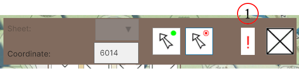
- Fail: a ‘!’ is shown as the marker failed to be placed at hex 6014 (no such hex in this case).
This modal panel is used to perform dead ground calculations. No other controls are available while the panel is open.
Close the panel in order to return to the normal map interface.
-
Range: enter the required range of the dead ground from the current source marker in hexes. Zero range means
‘no limit’.
-
OK: click this button to perform the dead ground calculation. The calculation cannot be interrupted and will run to
conclusion, so beware choosing zero as the range for a large set of map sheets for software running on slow hardware, as
it may take some time to complete. Try increasing the range and performing multiple calculations to determine the
performance of your particular hardware.
- Close panel: closes the panel.
The purpose of the following sections is to provide an example of how to perform certain tasks, identifying which tools to
use and when to use them. Using the Kernstown map of the Death Valley module, a source marker will be placed in hex 3813, a
target marker will be placed in hex 4215, a line of sight will be calculated between those hexes (with and without the Crest
optional rule), a dead ground analysis will be calculated from the source hex to a range of 5 hexes using the Crest rule, and
the map will be viewed from the source hex.
In order to place the source marker at hex 3813 on the Death Valley Kernstown map:
- Re-centre the viewer using ‘Home view’.
- Using ‘Move view mode’ and ‘Zoom view mode’, re-position the viewer so that hex 3813 can be seen.
- Select ‘Place source mode’.
- Click on hex 3813 to place the source marker.
Alternatively:
- Use ‘Text coordinates’ to open the ‘Coordinate Panel’.
- Type ‘3813’ into the ‘Coordinate’ text field.
- Click ‘Place source marker’ to place the source marker in hex 3813.
- Use ‘Close panel’ to close the panel and return to the mapping interface.
In order to place the target marker at hex 4215 on the Death Valley Kernstown map:
-
Re-centre the viewer using ‘Home view’ (this is not necessary if following the step above which placed the source
marker).
- Using ‘Move view mode’ and ‘Zoom view mode’, re-position the viewer so that hex 4215 can be seen.
- Select ‘Place target mode’.
- Click on hex 4215 to place the target marker.
Alternatively:
- Use ‘Text coordinates’ to open the ‘Coordinate Panel’.
- Type ‘4215’ into the ‘Coordinate’ text field.
- Click ‘Place target marker’ to place the target marker in hex 4215.
- Use ‘Close panel’ to close the panel and return to the mapping interface.
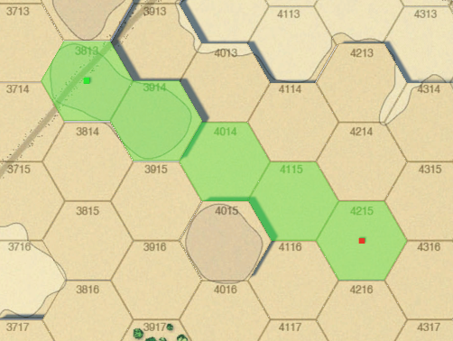
In order to calculate a line of sight from hex 3813 to hex 4215 on the Death Valley Kernstown map:
- Place the source marker at hex 3813 (‘How to place the source marker’).
- Place the target marker at hex 4215 (‘How to place the target marker’).
-
Check that ‘Crest’ is ticked and, if currently marked with a red ‘X’, click on ‘Crest’ to show the green tick. This
will cause the calculation to use the Crest optional rule.
-
Click ‘Line of Sight’, which will show the following result. The green highlighted hexes are considered unblocked,
while the red highlighted hexes are considered blocked. The change over from green to red indicates the location at which
the blockage occurs. If a blockage occurs, then a ‘Status’ message will be shown indicating the cause of the blockage.
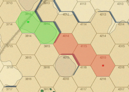
The message:
To perform the calculation without using the Crest optional rule:
- Place the source marker at hex 3813 (‘How to place the source marker’).
- Place the target marker at hex 4215 (‘How to place the target marker’).
-
Check that ‘Crest’ is marked with a red ‘X’ and, if currently marked with a green tick, click on ‘Crest’ to show the
red ‘X’. This will cause the calculation to not use the Crest optional rule.
-
Click ‘Line of Sight’, which will show the following result. The green highlighted hexes are considered unblocked,
while the red highlighted hexes are considered blocked. The change over from green to red indicates the location at which
the blockage occurs. If a blockage occurs, then a ‘Status’ message will be shown indicating the cause of the blockage.
To clear the current Line of Sight red/green calculation feedback, click ‘Clear Line of Sight’.
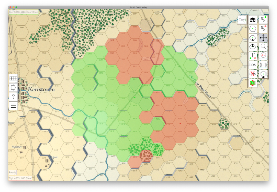
In order to calculate dead ground from hex 3813 out to a range of 5 hexes on the Death Valley Kernstown map:
- Place the source marker at hex 3813 (‘How to place the source marker’).
-
Check that ‘Crest’ is ticked and, if currently marked with a red ‘X’, click on ‘Crest’ to show the green tick. This
will cause the calculation to use the Crest optional rule (this is only done in this example so that the result image shown
below is correct. The Crest rule can be used or not used as you prefer).
- Use ‘Dead Ground’ to open the ‘Dead Ground Panel’.
- Type ‘5’ into the ‘Range’ text field.
-
Click ‘OK’ to perform the calculation, which will show the following result. The green highlighted hexes are considered
visible from the source hex, while the red highlighted hexes are considered not visible from the source hex. To determine
why a specific hex is not visible from the source hex, place a target marker in that hex and use ‘Line of Sight’ to perform
a single calculation to that hex and receive the ‘Status’ information.
- Use ‘Close panel’ to close the panel and return to the mapping interface.
To clear the current dead ground red/green calculation feedback, click ‘Clear Line of Sight’.
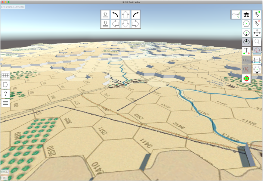
The goal of this exercise is to position the viewer so that the town of Kernstown on the Kernstown map can be seen from hex
2209 at the south end of Pritchard’s Hill.
To do this:
- Place the source marker at hex 2209 (‘How to place the source marker’).
- Click ‘Look down’ to place the viewer directly above, and looking down on, hex 2209.
-
Click ‘Stand on’ to adjust the viewer such that it sits in the centre of hex 2209 at ground level, looking out across
the map. You should see a view similar to that shown below. The ‘Stand on’ button remains grey as a reminder that when it
is clicked again, the viewer will return to the position it was in before the button was clicked, in this case looking
directly down onto hex 2209.
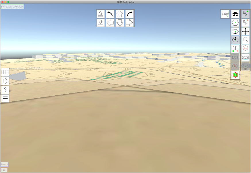
-
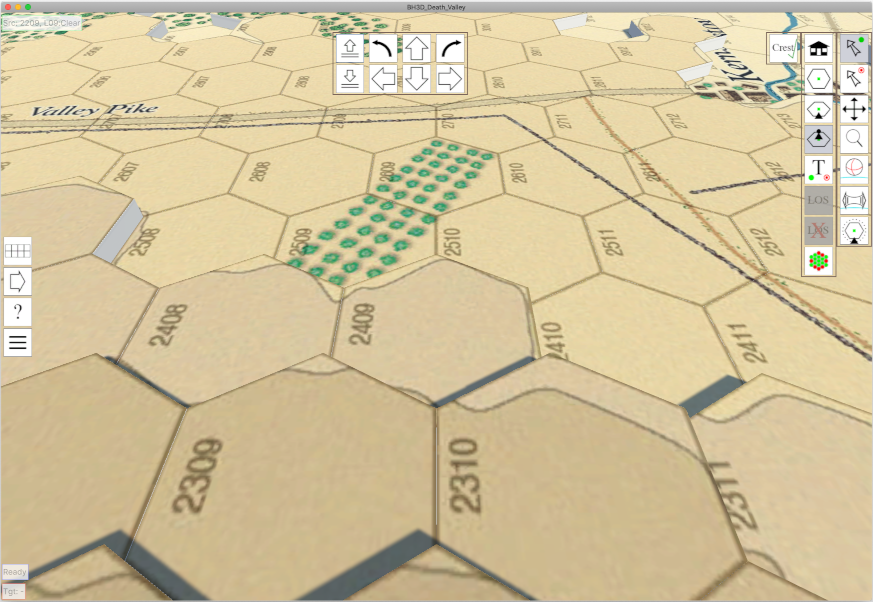
You can use ‘Turn view mode’ to swing the viewer around on the spot, but it will be difficult to see the Kernstown
hexes from this height. So, click ‘Move up’ twice, which will provide a view of the hexes around 2209. You should see a
view similar to that shown below. This view can be adjusted to see the surrounding area using ‘Rotate view mode’ and
‘Turn view mode’.
-
Now use ‘Rotate view mode’ and ‘Turn view mode’ to position the Kernstown hexes in the centre of the viewing window.
You should see a view similar to that shown below.
To top of page
Contact Information
support@dassedev.co.uk
(C) 2024 v0.1 16 Jan 2024